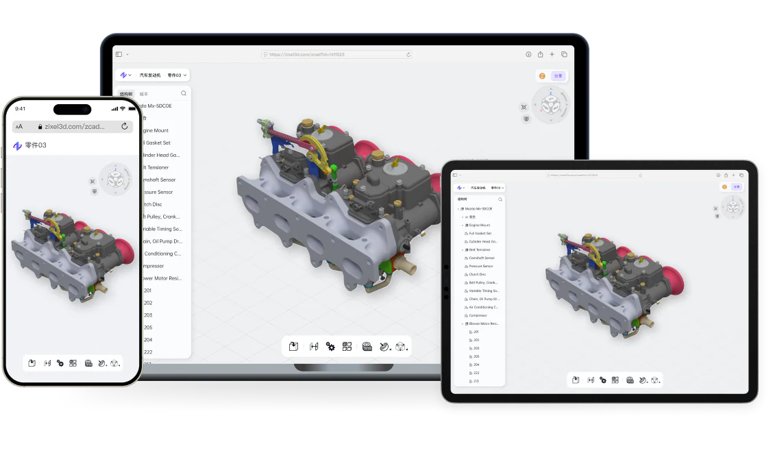
zCAD.Online running in a web browser across phone, laptop, and tablet with the same collaborative 3D CAD model

zCAD Online / Cloud-native parametric CAD

Parametric mechanical CAD, directly in the browser.

Create precise parts, large assemblies, specialized geometry, and engineering drawings in the browser. Keep automatic saving, versions, permissions, comments, sharing, and review connected to the current project.

Start designing online
  • Professional parametric modeling
  • Large assemblies and engineering drawings
  • Real-time collaboration and version control

zCAD Online

A complete parametric workspace in the browser.

Move from controlled geometry to assemblies, specialized modeling, drawings, project history, review, and engineering delivery without separating the model from its working context.

01

zCAD Online / Browser-based CAD

A full CAD modeling workspace in the browser

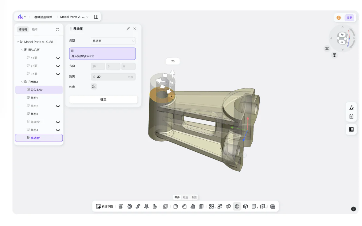
zCAD Online is built for creating and developing mechanical product data, not only opening a file after the modeling work is finished. Start a new parametric design or bring supported CAD data into the browser. Build features, organize components, prepare drawings, and continue the project through review and engineering change.

The distinction matters because “online CAD” can describe several very different tools. A viewer helps someone inspect existing geometry. A review portal helps collect feedback. A full modeling product must also let the engineer create and revise the product definition itself.

zCAD Online brings these activities into one browser-based workspace. The engineer can work directly with the model while versions, permissions, comments, sharing, and review remain connected to the current project. The result is a cloud CAD workflow centered on authoring—not a viewer with a modeling claim added to it.

02

zCAD Online / Browser-based CAD

See the model, structure, and project together

Three connected product views make the browser workspace concrete before the detailed feature sections: model and product structure, parametric detail and drawing, and version and review context.

01

Model and product structure

A multi-level assembly remains navigable in the modeling canvas while the product structure stays visible. Select a component in the assembly, return to the part that needs to change, and keep its surrounding interfaces available for inspection.
02

Parametric detail and drawing

A part carries its sketch, feature history, and controlled dimensions into the related engineering drawing. The connection makes “parametric” and “model-linked” visible in the product rather than leaving them as feature-list language.

03

Version and review context

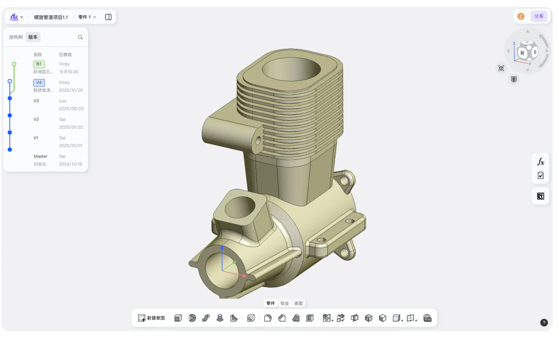
Project history, version comparison, and contextual comments refer to current geometry. Collaboration is attached to a known design state rather than presented as a generic chat panel beside CAD.

03

zCAD Online / Browser-based CAD

Build precise geometry with parametric control

Parametric modeling records the decisions that create the shape. A sketch defines profiles and relationships. Dimensions control measurable values. Constraints preserve conditions such as alignment, symmetry, tangency, or concentricity. Features turn those definitions into solid or surface geometry. References connect later work to earlier design decisions.

In zCAD Online, these elements form an editable design history. Instead of treating the model as a fixed shape, the engineer can return to the parameter or feature that represents the intended change. A mounting hole can move through its controlling dimension. A plate can become thicker without rebuilding every following operation. A referenced face or datum can keep related features aligned with the design.

This structure is important for routine engineering change. Requirements rarely remain fixed from the first sketch to final delivery. Testing, supplier feedback, packaging limits, material choices, and manufacturing processes all introduce new constraints. Parametric CAD allows the model to respond through explicit relationships rather than through repeated manual reconstruction.

01

Sketches, dimensions, and constraints

Create controlled two-dimensional definitions for features and interfaces. Use dimensions to represent size and position, and constraints to preserve geometric relationships that should remain true through revision.

02

Feature-based modeling

Develop parts through an ordered sequence of engineering operations. The feature history provides a readable path back to the decision that needs to change and a structured basis for downstream geometry.

03

References and design intent

Use planes, datums, faces, axes, and other references to connect features deliberately. Stable references help changes propagate through the model in a way that reflects the intended product logic.

04

zCAD Online / Browser-based CAD

Develop parts into multi-level assemblies

A product is more than a collection of isolated components. Assemblies define how parts are grouped, positioned, repeated, and related across the product structure. zCAD Online supports work from individual parts to large, multi-level assemblies in the same browser-based design environment.

Engineers can create components, place them in assemblies, and organize subassemblies to reflect the real structure of the product. Controlled component relationships help communicate how parts connect and how a change in one location may affect surrounding geometry.

This view is necessary for more than presentation. Assembly context supports interface checks, packaging decisions, access around fasteners, mechanism development, and the review of component positions. It also provides the product structure needed when drawings and manufacturing information are prepared for individual parts or larger systems.

01

Work at the right level of detail

Edit a single part when the decision is local. Return to assembly context when the change depends on neighboring components or a shared interface. Organize subassemblies so teams can understand the product at a useful level instead of navigating an unstructured list of files.

02

Keep component relationships visible

When a bracket moves, a shaft diameter changes, or an enclosure becomes smaller, the surrounding product may also need attention. Assembly structure keeps these relationships available for inspection before the change reaches documentation or production.

05

zCAD Online / Browser-based CAD

Create specialized mechanical geometry

Mechanical products require more than basic prismatic parts. zCAD Online includes workflows for sheet metal, weldments, advanced surfaces, and other detailed geometry within the same product environment.

01

Sheet metal

Develop formed components while preserving the relationships that matter to the design and its downstream preparation. Keep sheet-metal work connected to the assemblies and drawings in which the part is used.

02

Weldments and fabricated structures

Create structural and fabricated geometry for frames, equipment, and machine components. Organize the resulting members and details as part of the wider mechanical product rather than as a separate modeling exercise.

03

Advanced and freeform surfaces

Build or refine geometry where product form, transitions, or complex boundaries require surface-based methods. Continue from surface definition into the part and assembly context needed for the rest of the engineering workflow.

The purpose of these capabilities is continuity. A specialized part should not lose its connection to product structure, documentation, versions, or review simply because its geometry requires a different modeling method.

06

zCAD Online / Browser-based CAD

Turn the model into engineering documentation

The 3D model is central to the product definition, but engineering work still needs clear downstream communication. zCAD Online supports model-linked engineering drawings with dimensions, annotations, and manufacturing information.

Drawings provide a controlled view of the part or assembly for people who may not work directly in the 3D authoring environment. They identify critical dimensions, communicate annotations, and organize the information required for review, sourcing, or manufacturing conversations.

Keeping drawings linked to the model reduces the distance between a design change and the documentation that must reflect it. When geometry changes, the engineer can return to the related drawing, inspect what is affected, and update the communication before delivery.

Documentation is therefore not treated as decoration applied after modeling. It is one of the outputs of the engineering definition and part of the same continuing workflow.

07

zCAD Online / Browser-based CAD

Keep project history and review connected to the model

Cloud CAD should provide more than remote file storage. zCAD Online keeps the current model, automatic saving, meaningful earlier states, project access, comments, sharing, and review in one browser project.

01

Save work as part of the project

Automatic saving keeps design activity associated with the project instead of relying on a manual sequence of local filenames. The latest decision is less likely to remain isolated in an unsaved desktop state or an attachment whose status is unclear.

02

Return to a known version

Project history provides earlier states that can be inspected, compared, or restored. When a design direction changes, the team can understand what happened before the current version rather than searching through files named “final,” “final-new,” and “final-approved.”

03

Control access and review the right state

Permissions define who can enter the project and participate in the work. Comments and shared review refer to the relevant geometry and version, so a supplier, manufacturing partner, or internal reviewer can identify the design state under discussion.

The value is a clearer engineering decision. A reviewer inspects the current geometry, returns feedback against a known state, and the engineer continues the revision with the reason for the change still available. Company release and approval processes gain a more traceable model history to work with.

08

zCAD Online / Browser-based CAD

From first feature to engineering delivery

Consider a machine subassembly that includes a fabricated frame, mounted components, guarding, and several custom brackets.

  1. 01

    Create or import

    Start the project with a blank parametric model or supported imported CAD data. Establish the key interfaces, overall envelope, and reference geometry that will control the design.

  2. 02

    Develop the product

    Create the custom parts, organize the frame and purchased components, and build multi-level assembly structure. Use sheet metal, weldment, surface, or solid modeling methods where each component requires them.

  3. 03

    Check relationships

    Inspect clearances, mounting positions, component access, and the effect of changes across the assembly. Return to dimensions, constraints, features, and references when an interface needs adjustment.

  4. 04

    Document the design

    Prepare model-linked drawings with the dimensions, annotations, and manufacturing information needed for fabrication, review, or supplier communication.

  5. 05

    Review the change

    Share the current project with the appropriate participants. Collect comments against the relevant design state, preserve versions, and make the next revision with the reason for the change still visible.

  6. 06

    Deliver supported engineering data

    Export the supported CAD, drawing, or manufacturing data required for the next step. Keep the editable zCAD Online project as the continuing source for later revisions.

    This sequence is not a fixed template for every company. It shows how modeling, product structure, documentation, history, and review can remain connected instead of being divided into unrelated phases.

09

zCAD Online / Browser-based CAD

Start from existing CAD and evaluate a representative project

Not every design begins in a blank workspace. zCAD Online can start from supported imported CAD data and export supported engineering formats for downstream work. Exact format, version, and data behavior can be matched to current product documentation and the requirements of the project.

A useful evaluation follows representative data through a meaningful change. Include a typical component, an assembly with real interfaces, the drawing or exchange data required downstream, and one revision that affects the surrounding product.

  • Product designers: build editable product geometry and test whether dimensions, features, and relationships remain clear as the concept develops.
  • Mechanical engineers: create or import the part, place it in assembly context, change a controlled definition, and update its engineering drawing.
  • Reviewers and manufacturing partners: inspect the current project, identify the relevant version, and return feedback against the geometry under discussion.
  • Engineering and CAD managers: evaluate project access, permissions, versions, documentation, review, and data exchange across the complete pilot.

The evaluation should answer practical questions. Can an engineer find and change the controlling definition? Does the assembly expose the effect of that change? Can the reviewer identify the correct state? Does the drawing remain part of the workflow? Can the required data reach the next engineering or manufacturing step?

These answers reveal more than a feature checklist because they show how zCAD Online behaves when the project continues beyond the first successful model.

10

zCAD Online / Browser-based CAD

Choose the correct zCAD workflow

Use zCAD Online when you need direct parametric modeling, parts, assemblies, specialized geometry, engineering drawings, project history, permissions, comments, sharing, and browser-based review.

Use the online CAD viewer when the current task is limited to opening and inspecting existing model data without authoring the design.

Use zCAD AI when the task begins with a written engineering requirement and a prompt-led route to structured CAD generation and revision is more appropriate than direct feature authoring.

Mechanical CAD tools for the complete product-design workflow.

Move from controlled geometry to complex product structure, manufacturing documentation, and collaborative review without separating the model from its engineering context.

01 / 03

Precise parametric parts and large assemblies

Create feature-based parts and multi-level assemblies with controlled dimensions, constraints, component relationships, and reusable design intent.

  • Dimension- and constraint-driven features
  • Multi-level assembly structures
  • Editable feature and design history
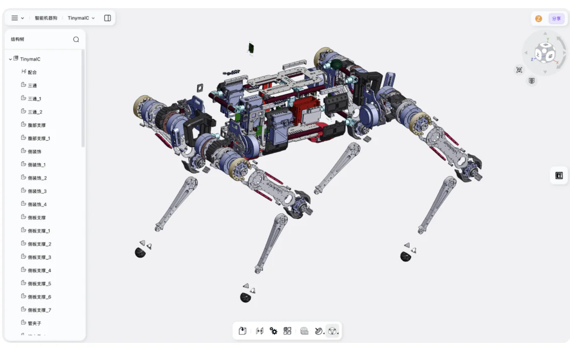
zCAD Online workspace showing the exploded structure of a complex quadruped robot assembly

Start designing in the browser.

Create precise parametric models, engineering drawings, versions, and reviews in one cloud-native CAD workspace.