zCAD AI / PROMPT-LED STRUCTURED CAD

Turn engineering intent into structured CAD.

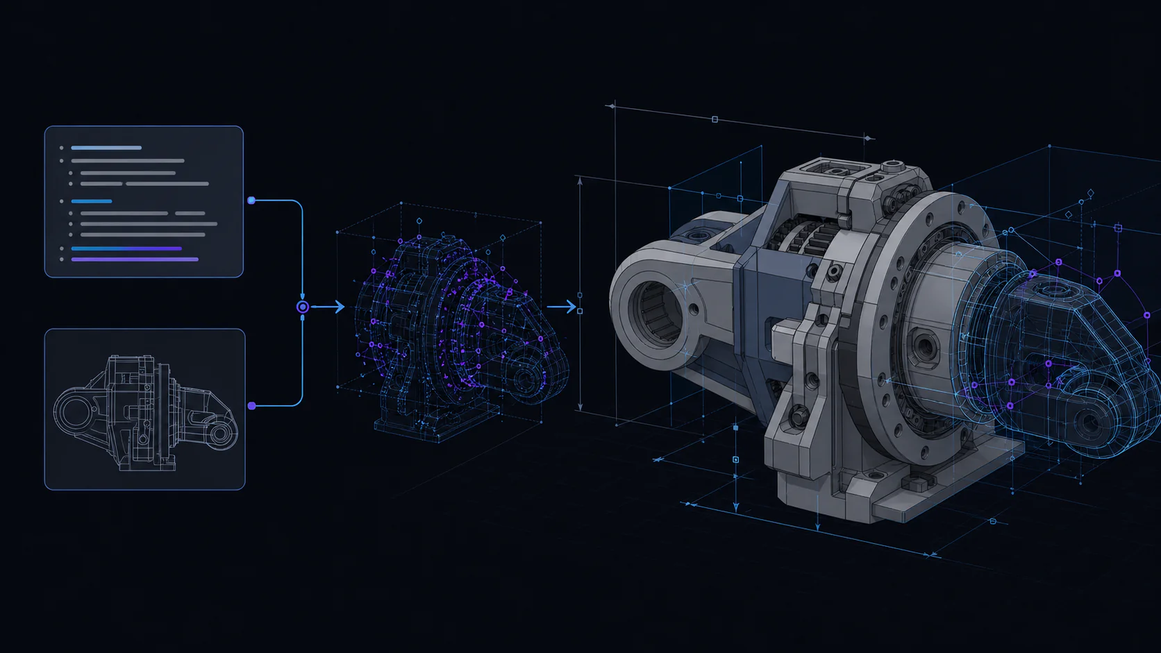
Describe what the part must do. zCAD AI translates the request into a CAD model you can inspect, revise, and continue toward manufacturing.

  • Prompt-led modeling
  • Structured CAD output
  • Controlled follow-up revision
Explore how it works

zCAD AI

From engineering intent to structured CAD.

Describe what a part must do, inspect the structured result, and continue the model through controlled follow-up changes. The goal is usable CAD, not a picture that only looks like a part.

01

zCAD AI / Intent to structured CAD

Shorten the distance from an idea to a manufacturable part

The larger opportunity for AI CAD is not simply completing familiar commands faster. It is giving people who understand a product, mechanism, manufacturing process, or engineering problem a more direct way to turn that knowledge into an editable model.

Today, the path into CAD is often limited by who has spent years mastering a demanding interface. That expertise remains valuable, but the interface should not be the only route from engineering understanding to a precise product definition.

zCAD AI moves the starting point closer to intent. Describe the function, interfaces, dimensions, and conditions that matter; receive structured CAD that can be inspected; then continue the design through controlled revision. More of the user’s attention can stay on requirements, tradeoffs, failure modes, and the decisions that determine whether a product should be made.

This is what “toward manufacturing” means for zCAD AI. The model is created to continue into the engineering decisions required for a physical part. Material, process, tolerance, load, compliance, quality, and production requirements remain part of responsible validation, while the distance between an idea and an engineering model becomes shorter.

02

zCAD AI / Intent to structured CAD

The slow part is often the translation into CAD commands

An engineer can understand a part before a CAD feature exists. The function may already be clear: hold components at a fixed distance, fit inside a known envelope, preserve fastener access, or connect to an established mounting pattern.

Conventional CAD still requires that decision to be translated into a sequence of interface operations. Choose a plane. Construct a sketch. Add dimensions and constraints. Create a feature. Select a reference. Repeat the pattern. Reorder the history when an early assumption changes. The operations create necessary structure, but performing them is not the same as making the original engineering decision.

Consider a simple bent bracket: a base plate, two mounting holes, one upright face, and a clearance requirement around a neighboring component. The function can be described in a few sentences. Building the model conventionally still requires a series of choices about profiles, bend position, hole references, feature order, and parameter control.

zCAD AI is designed to reduce this translation cost. The user begins with the part’s purpose and defining conditions. The product converts more of that requirement into structured CAD, presents the model for inspection, and keeps the next revision in the same prompt-led workflow.

The objective is not to hide engineering. It is to let the engineer spend more attention on what must be true and less attention on expressing every decision as a separate interface command.

03

zCAD AI / Intent to structured CAD

Not a picture of the part. The part.

Visual 3D generation can quickly turn an idea into an image or approximate shape. That is useful for visual work. Engineering has a different standard.

A mechanical part must be measured. Its interfaces must fit. Its clearances must be checked. Its wall thickness, hole positions, datums, symmetry, and feature relationships may need to remain controlled. A supplier or reviewer may request a change that affects one condition but not the rest of the design.

For AI CAD, the result cannot end at visual plausibility. The product standard is a CAD model that can be inspected against requirements and continued through revision.

01

Precise enough to inspect

The model should expose the geometry needed to evaluate dimensions, interfaces, clearances, and other conditions that determine whether the part works. Inspection must refer back to the original requirement, not only to the rendered appearance.

02

Structured enough to change

A hole should remain an identifiable design element whose position or size can change. A wall thickness should remain a meaningful condition. Repeated features, symmetry, references, and interfaces should preserve more than the visible surface of the result.

03

Clear enough to question

When a requirement is incomplete, a finished appearance should not hide the assumptions or prevent the user from correcting them in the next prompt.

04

Ready for the next engineering decision

Testing, design review, supplier constraints, material choices, and manufacturing feedback all create another version. AI CAD becomes useful when it supports that next decision rather than optimizing only for the first generation.

04

zCAD AI / Intent to structured CAD

One requirement. One model. One controlled change.

Follow one engineering task from the initial requirement through inspection and revision.

  1. 01

    Initial requirement

    Create an L-shaped mounting bracket that holds a sensor 40 mm above a base plate. Use two symmetric 6 mm mounting holes on the base, keep the upright face centered between them, maintain 3 mm wall thickness, and leave 12 mm clearance behind the sensor. Preserve the base hole pattern if the bracket height changes.

  2. 02

    Generated structure

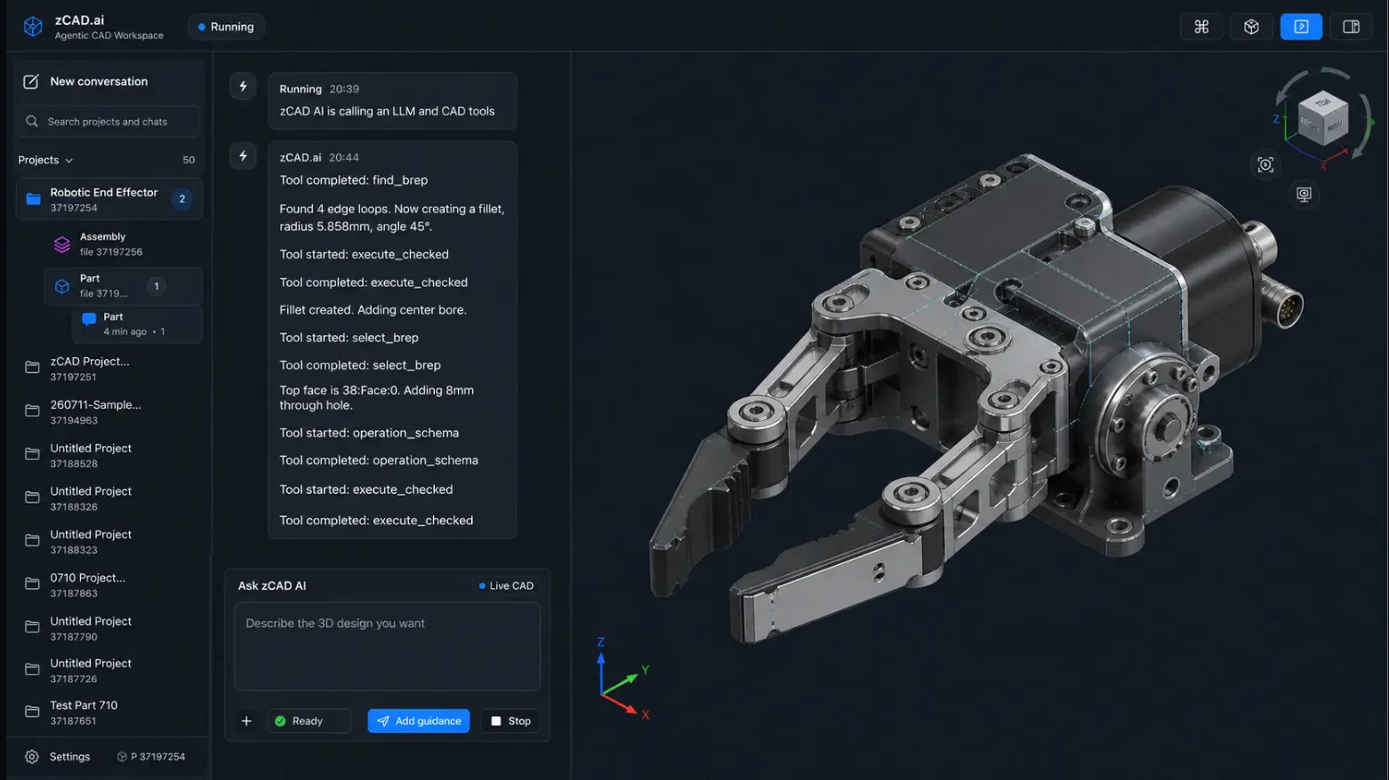
    The product view connects the written requirement with the model and its Feature Plan or modeling structure. The base profile, upright feature, mounting holes, controlled wall thickness, and clearance condition remain visible as parts of the result rather than disappearing into a rendered surface.

  3. 03

    Engineering inspection

    The 40 mm sensor position, two 6 mm holes, 3 mm wall thickness, and 12 mm clearance provide measurable checks. Symmetry and the base datum make the mounting relationship clear, while any condition missing from the request remains available for the user to question and refine.

  4. 04

    Follow-up change

    Increase the sensor height from 40 mm to 55 mm. Preserve the base hole pattern, 3 mm wall thickness, and 12 mm rear clearance.

    The revised state makes the product standard visible: the height changes, the protected relationships remain fixed, and the result can be compared with the original requirement.

05

zCAD AI / Intent to structured CAD

Structured CAD carries the logic behind the shape

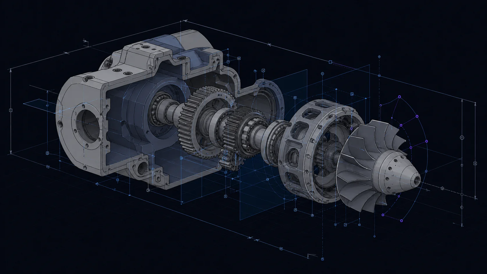
Dimensions express controlled values. Constraints preserve geometric conditions. Features record operations with engineering meaning. References connect one decision to another. Together they turn geometry into a model that can be understood and revised.

Two models may look identical in a rendered image while behaving very differently when the requirement changes. One may contain a symmetric hole pattern tied to a mounting datum; the other may contain surfaces with no meaningful connection to the interface. zCAD AI is built around structured CAD because the second and third decisions reveal as much value as the first result.

06

zCAD AI / Intent to structured CAD

Describe the engineering intent

A useful request gives the model a job and identifies the relationships that make the design valid:

  1. Part and function: Name the part and explain what it supports, connects, protects, positions, or guides.
  2. Overall geometry: Describe the main form, orientation, or envelope.
  3. Interfaces: Identify mounting patterns, faces, shafts, connectors, datums, or mating conditions.
  4. Controlled requirements: Provide the dimensions, clearances, thicknesses, symmetry, and patterns that determine fit or performance.
  5. Preserve during revision: State which interfaces, dimensions, or relationships should remain fixed when another condition changes.

Material, process, tolerance, load, and regulatory requirements can be added when they are known. Clear engineering conditions give zCAD AI a stronger basis for generation than a long list of decorative adjectives.

07

zCAD AI / Intent to structured CAD

From a written requirement to a revisable CAD model

  1. 01

    State the intent

    Describe the function, interfaces, controlled dimensions, and conditions to preserve. Separate fixed requirements from preferences so the model can prioritize the right relationships.

  2. 02

    Generate structured CAD

    zCAD AI interprets the request and creates the CAD result through a structured modeling workflow. The model and Feature Plan give the user a basis for understanding how the requirement became geometry.

  3. 03

    Inspect the result

    Compare the model with the original conditions. Check the envelope, critical interfaces, dimensions, clearance, symmetry, feature placement, and any relationship that determines whether the part performs its job.

  4. 04

    Continue the revision

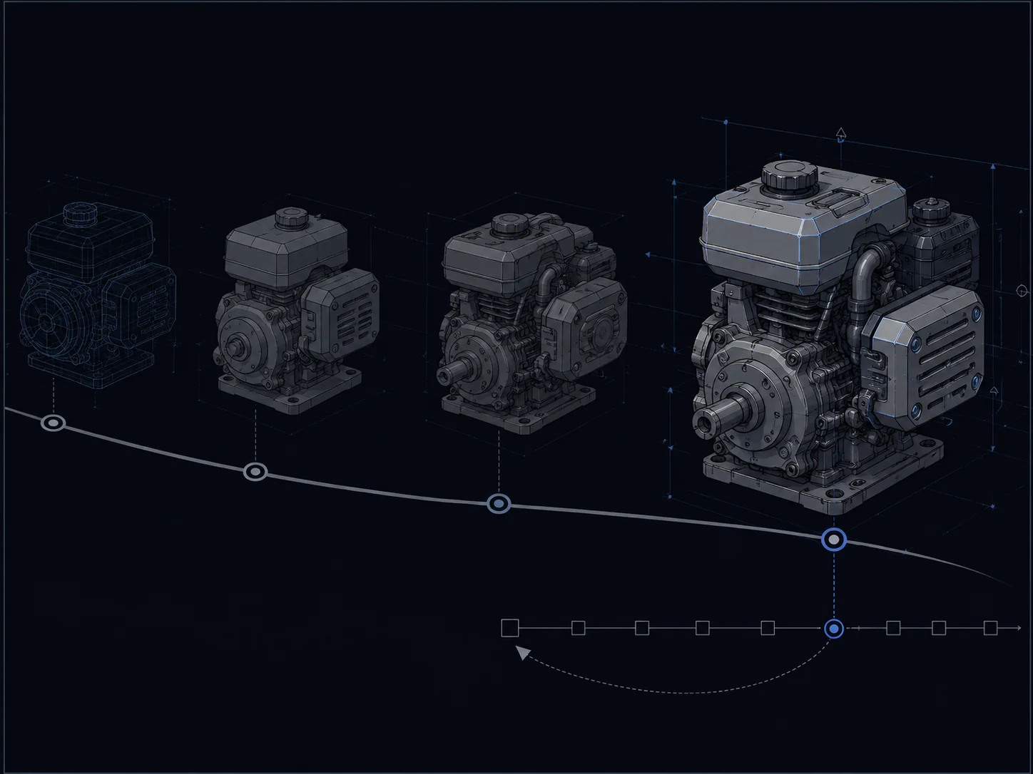
    Add a requirement, correct an assumption, change a dimension, or preserve an interface through a follow-up prompt. The next decision remains connected to the same modeling intent.

    This changes the unit of interaction. The user communicates a group of engineering conditions, inspects their translation into CAD, and continues with the next decision instead of expressing every step as an isolated interface command.

08

zCAD AI / Intent to structured CAD

Inspect the result like an engineer

Start with function: confirm that the geometry provides the support, access, protection, motion, or connection described in the request. Then check the interfaces that connect the part to the wider product, including mounting patterns, mating surfaces, shafts, connectors, and reference datums.

Measure the controlled dimensions, clearances, thicknesses, and positions. Test a meaningful revision, such as increasing a height while preserving a base pattern or changing wall thickness while keeping an outer interface fixed. The behavior under change shows whether the structure carries useful intent.

Conditions that were not supplied—such as load, material, tolerance, process, or compliance—remain engineering inputs for the responsible team. zCAD AI accelerates the modeling interaction while the user retains responsibility for validating the design against the full project requirements.

09

zCAD AI / Intent to structured CAD

AI CAD is not the same as an AI 3D model generator

An AI 3D model generator often optimizes for visible form, fast asset creation, rendering, or an approximate mesh. Those outputs can be valuable in visual workflows. Their success is usually judged by appearance and suitability for the target media.

AI CAD is judged by different questions. Can the geometry be measured? Are important dimensions and relationships represented? Can the user inspect interfaces and clearances? Does the model remain useful when a requirement changes? Can the result continue through an engineering workflow rather than ending as a visual asset?

zCAD AI is designed around the second standard. It turns written engineering intent into structured CAD and keeps generation, inspection, and follow-up revision in the same product workflow.

This distinction is why “Not a picture of the part. The part.” is more than a headline. It defines the threshold that an AI CAD product must cross before it is useful for physical product development.

10

zCAD AI / Intent to structured CAD

Choose prompt-led or direct parametric modeling

zCAD AI begins with engineering intent expressed through prompts. It is the product for generating, inspecting, and revising structured CAD through that prompt-led interaction.

zCAD Online begins with direct parametric authoring in the browser. Choose it when the engineer wants hands-on control over sketches, dimensions, constraints, features, parts, multi-level assemblies, specialized geometry, engineering drawings, versions, permissions, comments, sharing, and review.

Engineering intent becomes a model you can continue.

Generation is only the beginning. Inspect the feature plan and engineering detail, revise the model without losing context, and keep the result connected to the requirement.

Create CAD for manufacturing.

Describe what the part must do, inspect the structured result, and continue through controlled revision.

Create CAD for manufacturing